Introduction:
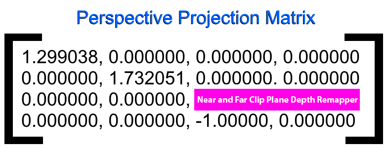
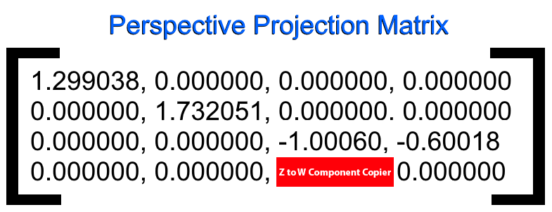
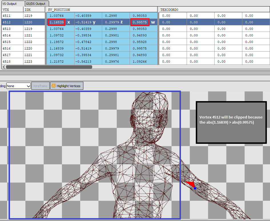
Take a look at the following image.
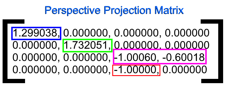
What do the highlighted numbers actually mean? Stop! No cheating! Don’t google the formula!
Most folks who make games are aware of the various transformations that must take place to render convert a 3d model from object or artist space to screen or pixel space. I think most folks also kind of understand what a projection matrix is. However, I find that many have trouble explaining what each number in a projection matrix actually means. The goal of this article is to take away the magic of those numbers and provide clarity with regards to what each number means in a projection matrix.
TL;DR
For those of us who don’t speak “internet” or its linguistic cousin “I’m too busy to type what I mean so you need to google my gibberish.” (Too long; Didn’t read)
The following is a list of important values in a perspective projection matrix along with the roles they serve.
- m00
- Controls how much the image is stretched or squashed horizontally. More specifically, m00 represents how much the image should be scaled horizontally relative to a 90-degree field of view. If m00 is 1, then the image will not be scaled at all. If m00 is 2, then objects will appear twice as big horizontally as they would be compared to a 90-degree field of view. m00 takes into consideration both the field of view and the aspect ratio.
- m11
- Controls how much the image is stretched or squashed vertically. More specifically, m11 represents how much the image should be scaled vertically relative to a 90-degree field of view. If m11 is 1, then the image will not be scaled at all. If m11 is 2, then objects will appear twice as big vertically as they would be compared to a 90-degree field of view.
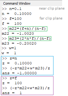
- m22 and m23
- Controls whether or not an object clipped based on its depth. The view space vector must exist within the camera’s near and far clip planes. m22 and m23 are also used to assist the rasterizer in converting the view space depth value into normalized device coordinate. The normalized depth value range is dependent on the rendering API. For OpenGL the ndc depth range is -1 to 1. For DirectX the range is 0 to 1. If you are using OpenGL and the ndc z value is -1, then the vector is on the near clip plane. If the ndc z value is 1, then the position is on the far clip plane.
- m32
- Enables the z component in your view space vector to be copied into the w component of the clip space coordinate. The z component in your view space vector represents the distance from your camera to the object along the camera’s z-axis. The w component plays a critical role in allowing the rasterizer to convert the clip space coordinates into normalized device coordinates which are then used to calculate screen space coordinates based on the viewport settings. If m32 is 0, the projection matrix is not a perspective projection matrix.
- If m32 is negative, then you are using a right-handed coordinate system. If m32 is positive, then you are using a left-handed coordinate system.
- When looking in a frame debugger like RenderDoc, you can instantly know if a clip space coordinate will be clipped or not.
A vertex will be clipped if the absolute value of any of the x y z components is greater than the absolute value of the w component.
3D Model Transformation Review:
Generally, you multiply an object space vertex position by a concatenated matrix which is composed of a world, view, and projection matrix. Below are details on what each matrix does.
- World Matrix (objectToWorldMatrix)
- Transforms object space vertices to world space vertices. I like to think of object space as the “artist” space as it is the space that the Artist models there geometry. All the vertices in the model, like a 3D character, are relative to some special place on the model. This special place is sometimes the model’s center of mass or at its feet. The world space matrix is the game world space in which all the 3d characters, vehicles, props, etc exist in.
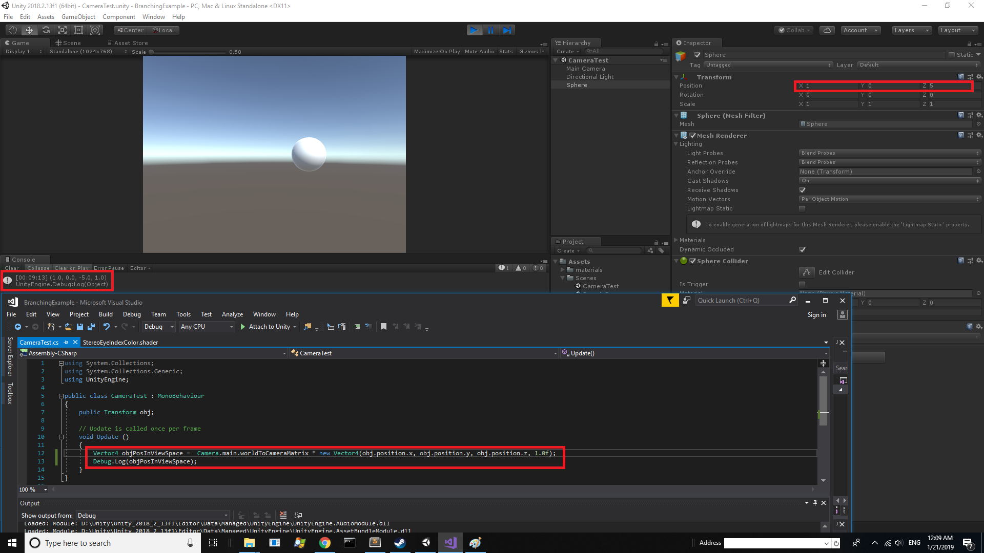
- View Matrix (worldToViewMatrix)
- The view matrix is responsible for transforming the world space vertices to view space. View space is relative to the camera. In view space, it is easy to determine where a 3d model is relative to the camera. For example, if a 3d character has a view space coordinate of [1,0,-5], then the model is 1 unit to the right of the camera and 5 units in front of the camera.
- Projection Matrix (viewToClipSpace)
- The projection matrix is responsible for transforming a vertex in view space into clip space. A lot of folks call this matrix a “projection” matrix. Really it should just be called a “clip space matrix” or “viewtoClipSpace” matrix because this matrix doesn’t actually project the view space coordinate onto anything. It simply transforms the view space coordinates into clip space coordinates.
What is the Role of the Projection Matrix?
The projection matrix ultimately serves 2 purposes.
- Convert view space positions into clip space positions.
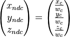
- Copy the view space z component so that the clip space coordinates can be converted to normalized device coordinates. The ndc space x and y components will be between -1 and 1 while the range of the z component will be dependent on the rendering API you use. For OpenGL, the ndc z component will be between -1 and 1 while in DirectX it will be between 0 and 1.
What is “Clip Space”?
Clip space is the coordinate system used to determine if geometry should be “clipped” or not. Take a look at the scene below.
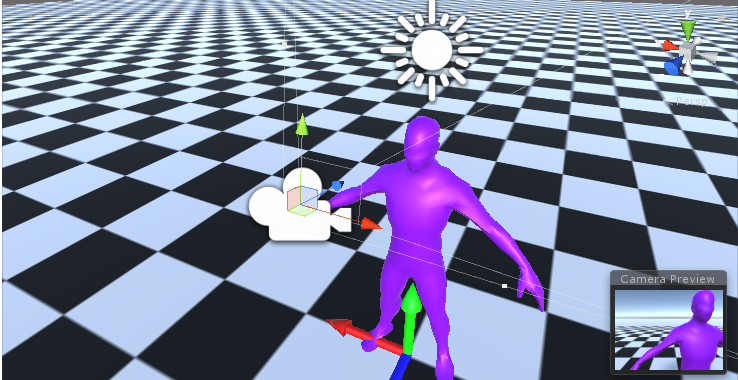
Pay attention to the lower right camera preview image. Notice that only a portion of the man is within the camera’s frustum. In a game, the player would see the following
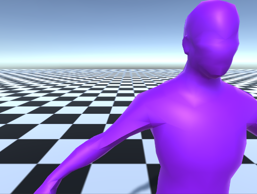
What happened to the man’s left hand, torso, and legs?
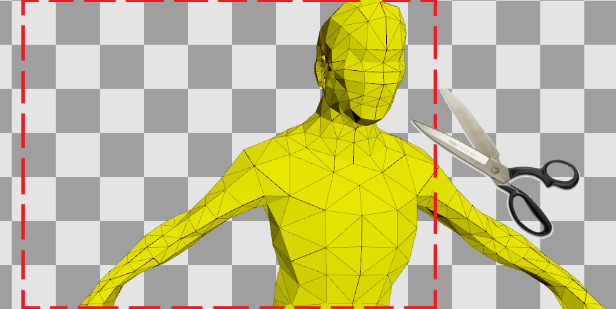
They were clipped off with the blade of math! Ok.. ok.. that was a bit much but you get the idea. If one of the man’s vertices is outside of the clipping rectangle, then those vertices will be clipped. You may ask, “What about triangles that have two vertices in the clipping plane and 1 outside of it?” Glad you asked! In that case, the GPU will still clip the vertex that falls outside of the clipping plane. However, the GPU will generate new vertices that don’t fall outside the clipping plane so that your triangles are still rendered.
What is the Point of Clipping Vertices?
Let me ask you a question. What is the point of calculating and shading vertices that you know you are never going to see?

Exactly! There is no point. Its a waste of precious GPU computation time. So just don’t do it! Fortunately, you don’t get much of a say anyway because the GPU is going to force clipping to happen whether you like it or not!
When Does Clipping Happen?

During rasterization, each primitive is converted into pixels, while interpolating per-vertex values across each primitive. Rasterization includes clipping vertices to the view frustum, performing a divide by z to provide perspective, mapping primitives to a 2D viewport, and determining how to invoke the pixel shader. While using a pixel shader is optional, the rasterizer stage always performs clipping, a perspective divide to transform the points into homogeneous space, and maps the vertices to the viewport.
https://docs.microsoft.com/en-us/windows/desktop/direct3d11/d3d10-graphics-programming-guide-rasterizer-stage
Understanding a Projection Matrix
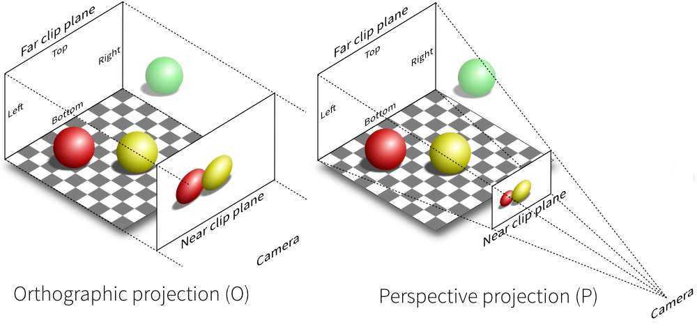
Image courtesy of https://glumpy.readthedocs.io/en/latest/tutorial/cube-ugly.html
There are various flavors of projection matrices. The two most popular as orthographic and perspective projection matrices. Orthographic projection matrices are commonly used in 2D games. The reason is that they project or map lines from view space onto your monitor’s flat screen without distorting the lines. The mapping of lines from one space to another is parallel. For example, imagine a typical 2D side scroller. The characters are 2D and flat. Therefore we just want to project the character onto the monitor without distorting any of the lines. In other words, as much as possible, we want to maintain a one to one from view space to screen space. On the other hand, a perspective projection matrix is typically used in 3D games like first-person shooters. Just like an orthographic projection matrix, a perspective projection matrix assists in mapping lines from view space to screen space. However, the main difference is that a perspective projection matrix distorts the lines. The amount of distortion or scaling that takes place is relative to how far away a line is from the camera. The further an object is from the camera, the more it will be scaled down. This allows a player to have a better sense of depth in a 3D game. If an enemy was going to attack you and you only had one bullet left in your gun, would you want to shoot him when he is closer to you or farther away? Most folks would choose to shoot him when he is closer because more of the enemy’s body would be in your field of view lessening the chance that your bullet would miss him. That is the kind of visual information a perspective projection matrix tries to provide.
When Does a Vertex Get Clipped?
Great question! The first thing you need to understand is that the GPU assumes that your camera’s field of view is 90 degrees. There is no way to inform the GPU as to what kind of field of view your camera should have. The GPU always assumes a 90-degree field of view. Take a look at the image below.
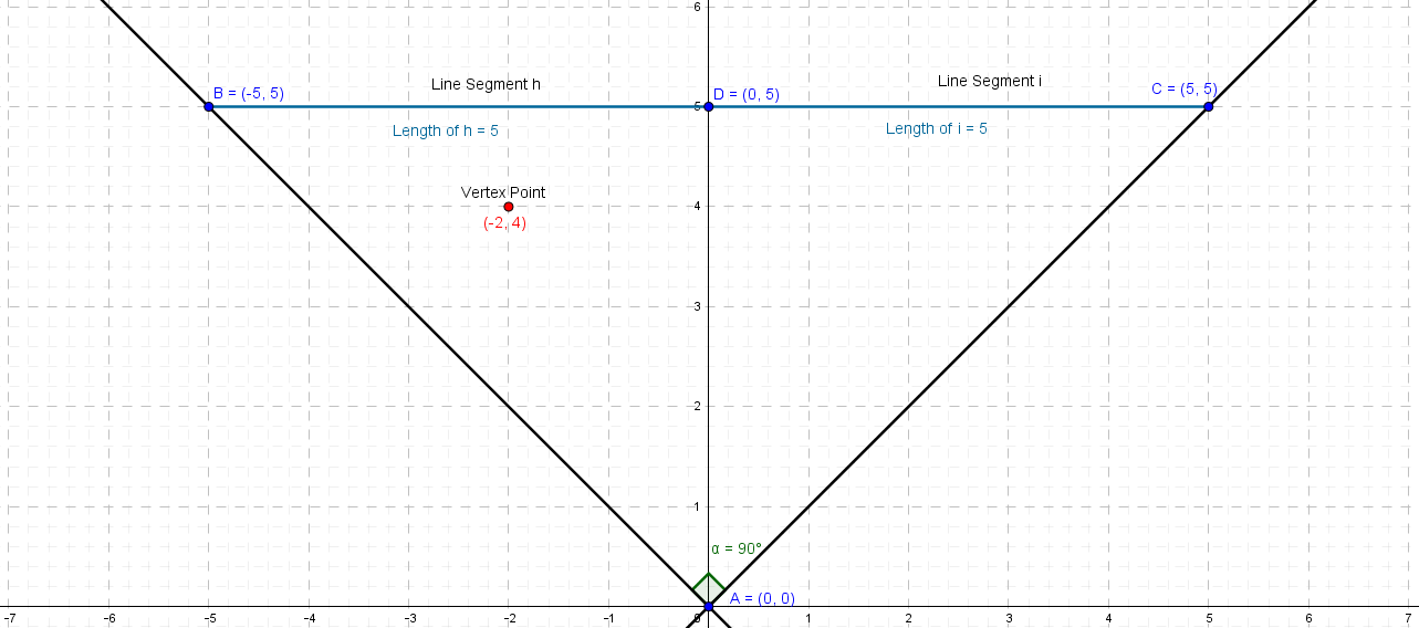
A point is inside a 90-degree field of view so long as the absolute value of an x-axis component is less than or equal to its y-axis component. In the image above, the x-axis value of the vertex point is -2. Its y-axis component is 4. The absolute value of -2 is 2 and 2 is less than 4, therefore, the vertex point in the example above will not be clipped. Now take a look at the following image below.
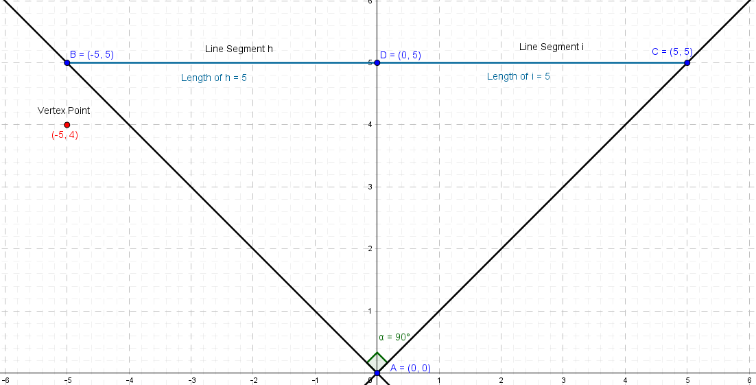
The vertex point is now located at -5,4. The x axis is -5 whose absolute value is 5. 5 is greater than 4 therefore the vertex point falls outside of the 90 degree field of view and will therefore be clipped out by the GPU.
How Do You Achieve a Non 90 Degree Field of View?
That is where the projection matrix comes in. In some ways, a projection matrix is a clever trick. It allows you to specify a scale factor that can either stretch or squash all the vertices in view space such that you can simulate non 90 degree field of views. The rasterizer’s clipping algorithm takes into consideration the x,y and z components of a vertex position.
How Horizontal and Vertical Clipping Works
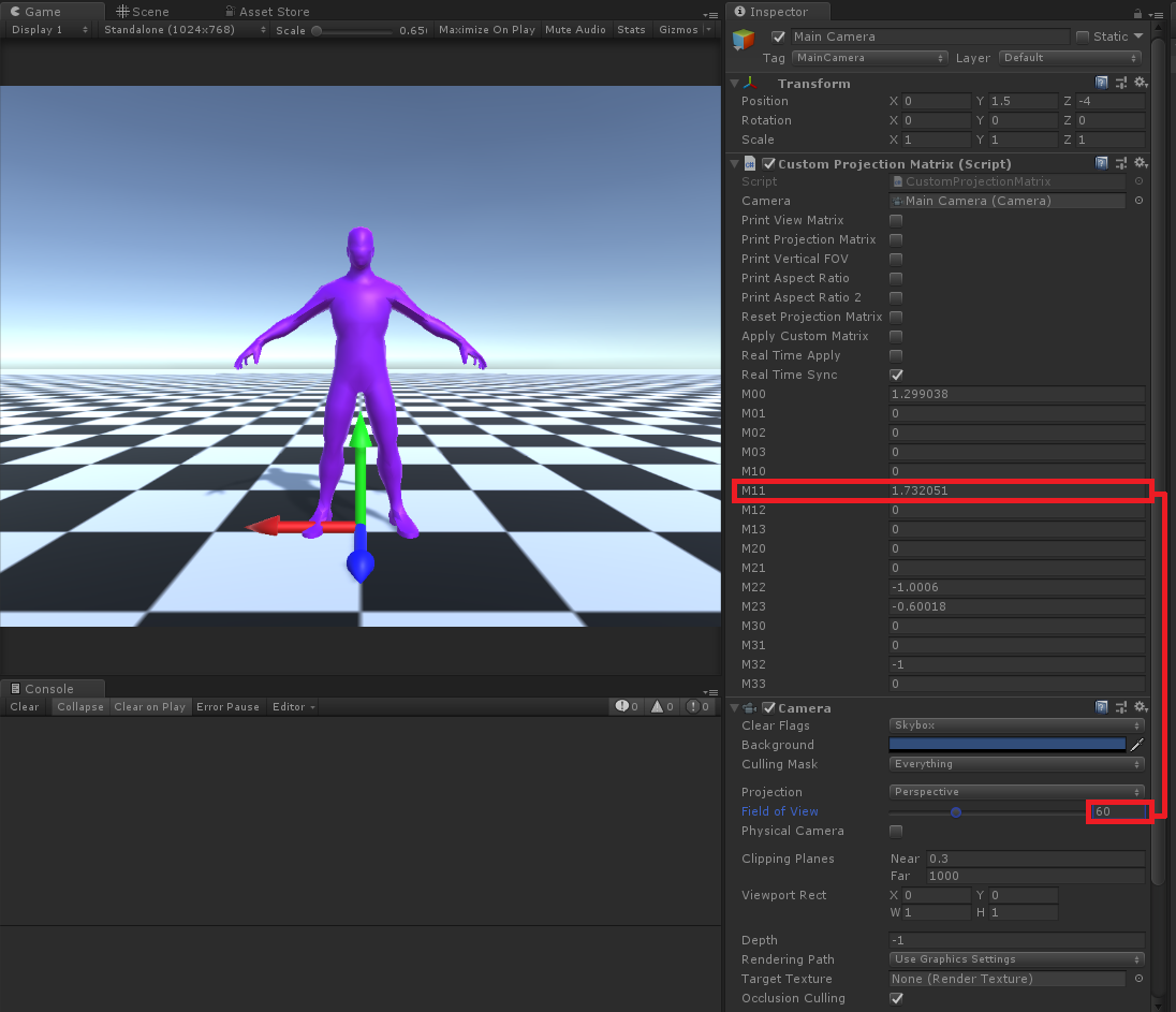
When you change the field of view property for a camera in Unity, you are actually controlling the vertical field of view. In the image below, I have set the camera’s field of view to 90 degrees.
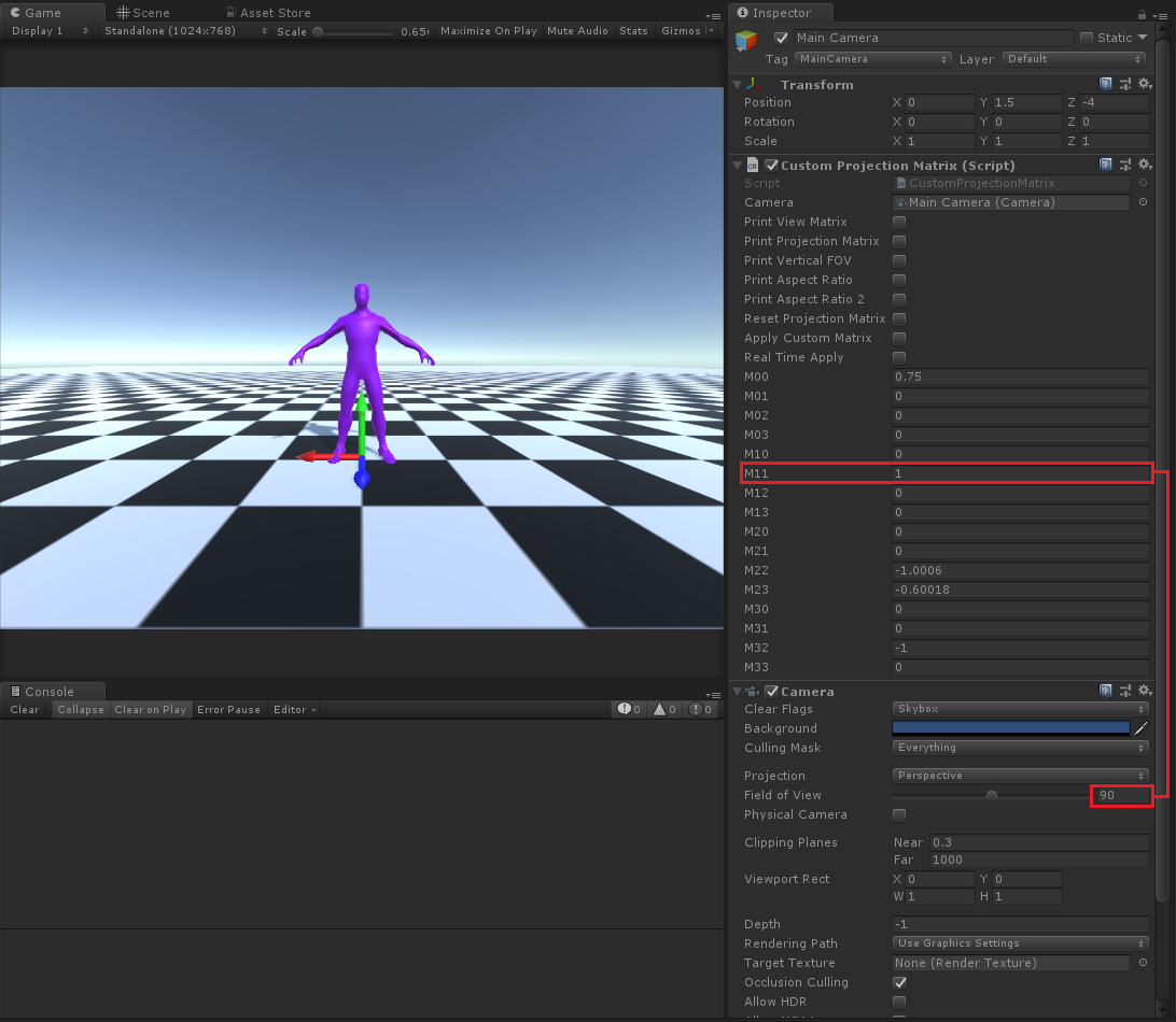
I have a custom projection matrix script that shows the raw values in the projection matrix. If you look at m11, you will find the value is 1. That is exactly what we would expect. If you recall, the GPU’s rasterization stage assumes the field of view is 90 degrees, therefore, we don’t need to stretch or squash the vertical field of view at all. We can simply leave it alone. However, notice that m00 is 0.75. m00 controls the horizontal scaling of the image. m11 controls the vertical scaling of the image. m00 is proportional to m11. When you set the field of view on the camera component, the engine calculates the horizontal field of view accounting for the game’s aspect ratio and then assigns the horizontal scale value to m00. Let’s see what would happen if you were to change m00 directly without taking the vertical field of view and aspect ratio into consideration.
Now lets see what would happen if we changed m11 independent of m00.
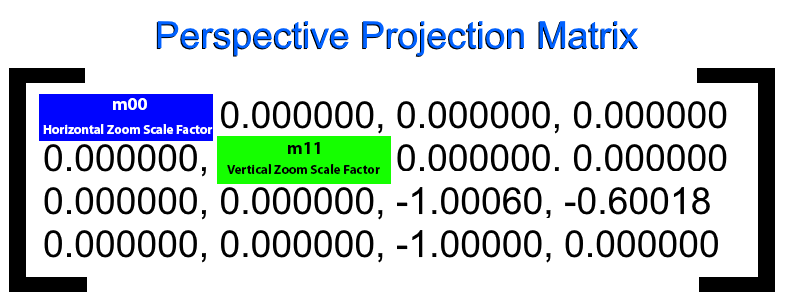
m00 and m11 are the horizontal and vertical zoom scale values.
Ultimately, we must exploit m00 and m11 to stretch or squash our vertices in such a way that we can simulate a non 90-degree field of view. Let’s take a look at how the vertical zoom scale factor is calculated. When you have a 90-degree field of view, the zoom value will be 1.
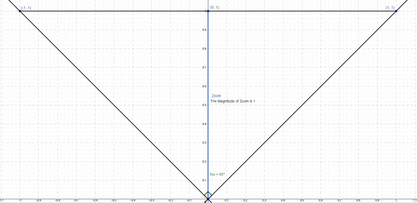
As we saw earlier, this is because a 90-degree field of view will always have the same max x and y values. What if our field of view was 60?
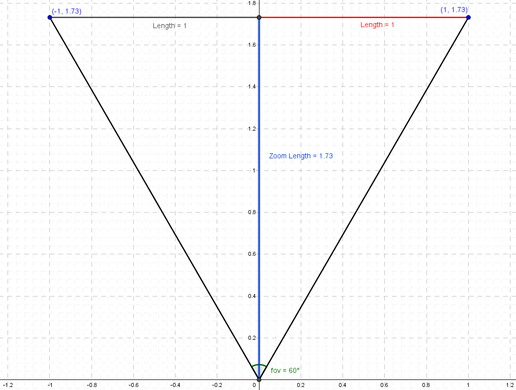
The zoom length for 60 degrees is 1.73. If you set the vertical field of view to 60 degrees in Unity, you will see the same zoom length value for m11.
As shown in the video clip below, the zoom length is directly related to the field of view.
We just need to use a little bit of trigonometry to calculate the zoom value. It is done like so.
|
1 2 3 4 5 6 7 8 9 10 |
// The Tangent is opposite / adjacent. // Our Adjacent line segment is our zoom value. In order to get that, // we do 1 / tan(fov/2) which gives us the zoom value. float halfFOVInRadians = (fov / 2.0f) * Mathf.DegToRad; float zoomLength = 1.0f/Mathf.Tan(halfFOVInRadians); // or using a trig identity we could do // float zoomLength = Mathf.Cos(halfFOVInRadians) / Mathf.Sin(halfFOVInRadians); // Update the Projection Matrix projectionMatrix.m11 = zoomLength; |
The horizontal zoom scale factor is calculated in almost the same way as the vertical zoom scale factor. The main difference is that the horizontal scale factor must take the aspect ratio into consideration so that the image doesn’t appear stretched or squashed incorrectly.
|
1 2 3 4 5 6 7 |
float aspectRatio = screenWidth / screenHeight; float halfFOVInRadians = (fov / 2.0f) * Mathf.DegToRad; float zoomLength = 1.0f/Mathf.Tan(halfFOVInRadians); // Update the Projection Matrix // zoomLength / aspectRatio == 1.0f/(Mathf.Tan(halfFOVInRadians)* aspectRatio) projectionMatrix.m00 = zoomLength/aspectRatio; |
Clipping Based on Depth
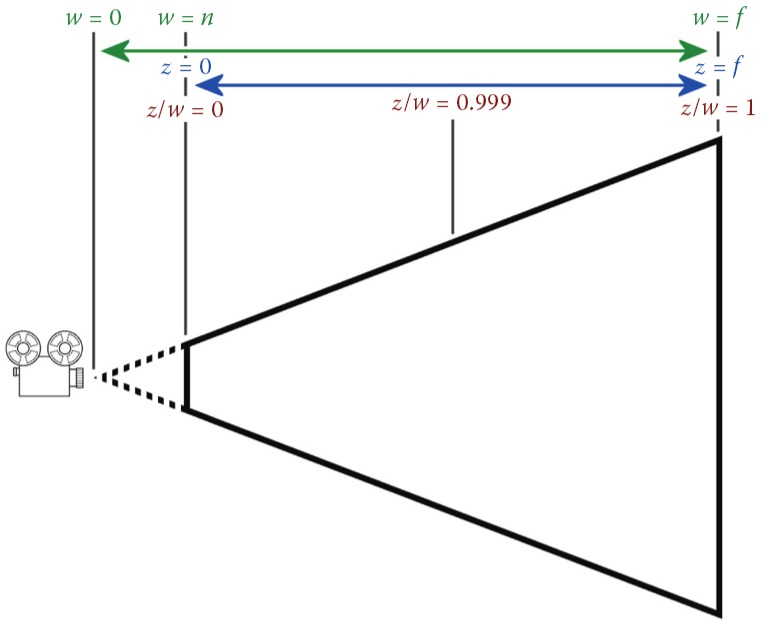
Together, the role of m22 and m23 is to map the view space z coordinate into clip space. The rasterizer will clip the vertex if it does not fall within the near and far clip planes. After the perspective divide, the clip space z component will be transformed into normalized device coordinates. As mentioned earlier, this is where things differ a bit based on your rendering API. OpenGL expects the normalized device coordinate z component to be within the range of -1 to 1. Whereas DirectX expects it to be between 0 to 1. Therefore the contents of m22 and m23 will be a bit different depending on the rendering API. Assuming the DirectX rendering API, if the normalized device coordinate z component is 0, then the vertex is on the near clip plane. If the normalized device coordinate z component is 1, then the vertex is on the far clip plane.
The following example assumes the OpenGL rendering API and demonstrates how m22 and m23 are calculated and used to map the view space vector to a normalized device coordinate within the range of -1 to 1. Z will be remapped to -1 when it is set to the near clip plane. Z will be remapped to 1 when it is set to the far clip plane. It’s important to note that the view space vector must have a w component value of 1! If w is 0, then m23 will be zeroed out and thus cause the mapping of z in normalized device coordinate space to b wrong!
|
1 2 3 4 |
// Remap a view space vector like <x,y,z,1> // into the range -1 to 1 after the perspective divide. projectionMatrix.m22 = (f+n)/(n-f); projectionMatrix.m23 = (2*f*n)/(n-f); |
The Z to W Component Copy
The purpose of the 1 in element m32 is to copy the view space vector’s z component into the clip space vector’s w component.
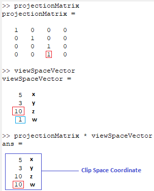
The view space vector’s z component represents the distance from the camera to the fragment. m32 will be negative when using a right-handed coordinate system and positive when using a left-handed coordinate system. This distance is needed in order to convert the clip space xyz components into normalized device coordinates in the range of -1 to 1. As noted earlier, DirectX will convert the clip space z component into the range of 0 to 1. The normalized device coordinates are used along with the viewport settings to transform a point from clip space into screen space coordinates. The normalized device coordinates are calculated by dividing each clip space coordinate by the clip space w component. However, you don’t need to do this manually. The GPU automatically handles the conversion to normalized device coordinates during the rasterization stage in a process called the “perspective divide“.
Perspective divide – “The clip-space positions returned from the clipping stage are transformed into normalized device coordinates (NDC) via this equation” – khronos.org
If m32 is negative, then you are using a right-handed coordinate system. If m32 is positive, then you are using a left-handed coordinate system. The handedness of your coordinate system determines which direction the z-axis is facing. In a right-handed coordinate system, if an object is in front of the camera, then it will have a negative z value. Whereas in a left-handed coordinate system, an object in front of the camera will have a positive z value. Take a look at the documentation for the following functions for more information.
In fact, that is what the GPU does as well to increase performance. If we were to convert the coordinates to normalized device coordinates first and then do clipping, we would waste a lot of divide by w operations for vertices that will never be displayed. Divides are not cheap therefore it is better to simply compare each x, y z component against w directly and if the components are within the -w to w range, we know the vertex will be visible.
Sometimes you may want to do a perspective divide manually in a fragment shader. This is because the GPU will automatically apply the perspective divide to a vertex output value using the SV_POSITION semantic.
|
1 2 3 4 5 |
fixed4 frag (float4 screenPos: SV_Position): SV_Target { float t = screenPos.x / _ScreenParams.x; return fixed4(t,0,0, 1.0); } |


|
1 2 3 4 5 6 7 8 9 10 11 12 13 14 15 16 17 18 19 20 21 22 23 24 25 26 27 28 29 30 31 32 33 34 35 36 37 38 39 40 41 42 43 44 45 46 47 48 49 50 51 52 53 |
Shader "Unlit/ScreenSpaceTest" { Properties { } SubShader { Tags { "RenderType"="Opaque" } Pass { CGPROGRAM #pragma vertex vert #pragma fragment frag #include "UnityCG.cginc" struct appdata { float4 vertex : POSITION; float2 uv : TEXCOORD0; }; struct v2f { float4 vertex : SV_POSITION; float4 clipSpacePosition : TEXCOORD0; }; v2f vert (appdata v) { v2f o; o.vertex = UnityObjectToClipPos(v.vertex); o.clipSpacePosition = o.vertex; return o; } float4 frag (v2f i) : SV_Target { //float t = i.vertex.x / _ScreenParams.x; // (i.clipSpacePosition.x / i.clipSpacePosition.w) will be in the range // -1 to 1 so we will remap it to the range of 0 to 1. float t = (i.clipSpacePosition.x / i.clipSpacePosition.w) * 0.5 + 0.5; float4 finalColor = float4(t, 0, 0, 1.0); return finalColor; } ENDCG } } } |
How Does Each Matrix Value Affect the Final Image?
The following video clip demonstrates how each component in a projection matrix affects the projected image.
Unity Projection Matrix Simulator
I have prepared an Excel-based Unity Projection matrix Simulator. The simulator can help you gain a more intuitive understanding of how Unity uses a projection matrix to calculate your vertices final screen space position.
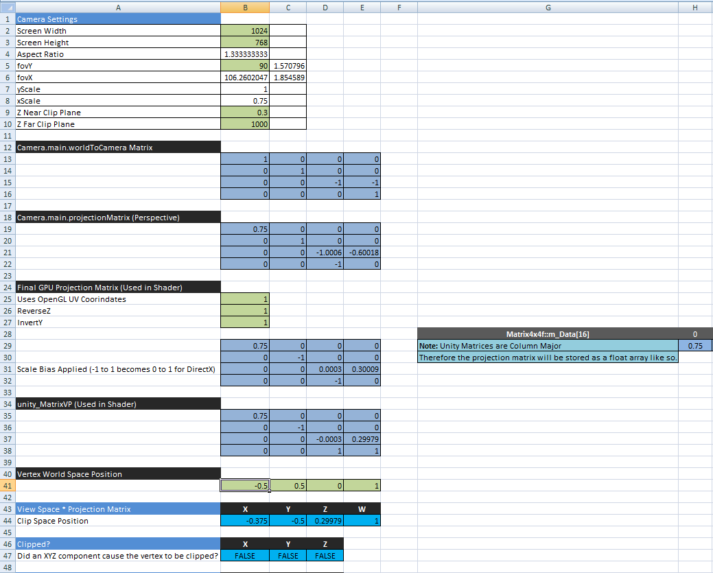
Internally Unity uses the OpenGL coordinate system. However, if you are using DirectX or reverse z depth buffering, Unity will automatically calculate the correct projection matrix before uploading it to the GPU. Be sure to use GL.GetGPUProjectionMatrix to convert any projection matrices not managed by a camera component.
Download the Excel Based Unity Projection Matrix Simulator
Download the Unity Custom Projection Matrix Project
Conclusion:
My hope is that this article has in some way given you a more intuitive understanding of the role each number in a projection matrix plays in projecting your 3D model into screen space. There are some values that I did not cover directly. For example, you can exploit values m02 and m12 to generate an asymmetric or off-center projection matrix. This kind of projection matrix is quite useful in virtual reality head-mounted displays. To get a better understanding of how m02 and m12 affect the projection, take a look at the video under the “How Does Each Matrix Value Affect the Final Image?” section. Watch how the image is distorted when m02 and m12 are modified. You can also exploit m11 and m00 to flip an image vertically or horizontally. Check out an article I wrote on that exact topic here. That’s it for now. If you liked what you read here, please follow me on twitter @bfogerty. Thanks for reading! Now go create something!